Aerobic System Inspection & Maintenance

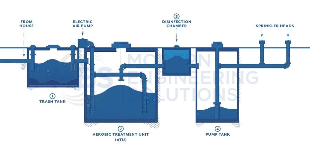
Aerobic System Inspection & Maintenance Aerobic treatment is a type of surface application that uses oxygen and or air to break down organic pollutants. The process of aerobic treatment is also known as activated sludge. The wastewater is mixed with microorganisms that feed on the organic pollutants. The mixture is then agitated to keep the microorganisms alive and breaking down the pollutants. Oxygen or air is then added to the mixture to help the process along. The wastewater then flows over a series of sloped surfaces which helps to separate the liquids from the solids. The liquids are then collected and discharged while the solids are dried and disposed of. The process is considered an anaerobic process because it does not use oxygen. The wastewater is mixed with microorganisms that feed on the organic pollutants. The process of aerobic treatment is one that uses a type of microorganism known as “bacteria”. The bacteria are allowed to produce enzymes that are toxic to the pollutants. The resulting toxins and organic wastes are then removed by the wastewater treatment plant. The activated sludge process is a technique for treating sewage. The process of aerobic treatment uses bacteria to help break down the pollutants in the wastewater. The toxic chemicals are then removed from the wastewater by a series of processes known as “biochemical oxidation”. The activated sludge process is a technique of sewage treatment that uses a biological agent to kill the microorganisms and promote the growth of organisms that can remove pollutants from the wastewater. Developer SERVICES Trinity Retail Plaza PROJECT Water and Wastewater Solutions SERVICES Arabian Acres Metropolitan District Treatment Improvement PROJECT Engineering Firms SERVICES Extraterritorial Jurisdiction (ETJ) BLOG
Types of Sewer Systems

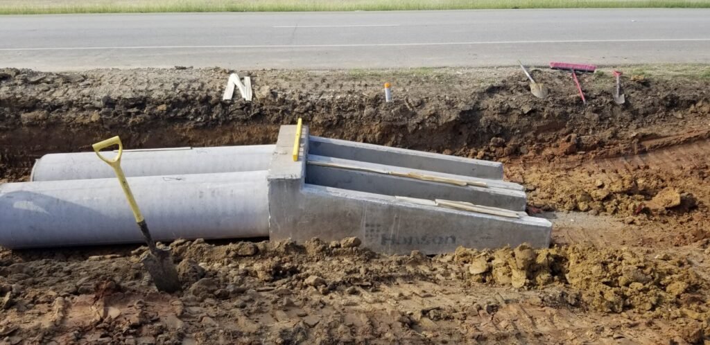
Types of Sewer Systems The Colorado landscape is dotted with Colorado land drainage systems, used to move water away from dry regions and into rivers and reservoirs. The state has more than 1,000 miles of canals and ditches, most of which were built in the 1800s to serve as a primary means of transportation and irrigation. Over time, many of these waterways have been replaced by paved roads or other forms of infrastructure, but they continue to play an important role in Colorado’s economy and culture. City planners must take into account many factors when designing a city, including the type of drainage system to be used. The most common type of drainage system is the underground storm sewer. This system consists of a network of pipes that collect rainwater and runoff from streets and other paved areas and carries it away from the city. There are several other types of drainage systems, each with its own advantages and disadvantages. Storm Sewer Systems Storm sewer systems are usually underground and carry away the water from streets and other paved areas. Sanitary sewers also carry sewage away from homes and businesses, as well as industrial waste. Combined sewer systems are underground networks that carry both storm water and sewage. Combined sewer systems are rarely used anymore and have been a big problem in major cities like New York City. Storm sewers are usually found in urban areas. They receive runoff from streets and other paved areas, as well as industrial waste, and carry that water away from the city. Sanitary Sewer Systems Private sewers are underground pipes that carry wastewater away from homes and businesses. Most private sewer service is provided by a private company, usually the same type of company that provides municipal services. In the United States, sewer systems are regulated by the U.S. Environmental Protection Agency (EPA), which uses a set of standards called the National Pollutant Discharge Elimination System (NPDES). The majority of sewer systems consist of a series of open-ended, underground pipes that carry wastewater from homes and businesses to a treatment plant, where it is treated. How Does City Drainage Systems Work? City drainage systems are made up of many different components that work together to move rain and snow out of the city and into rivers or oceans. The main components of a city drainage system are the storm sewer, street drainage, water main, and culverts. Typical storm sewers are open-ended, underground pipes that carry wastewater from rooftops to a treatment plant. They typically consist of pipe diameters from 12 inches to over 10 feet. The street drainage system is usually the primary means of transporting stormwater runoff from the roads to sewers. It consists of a network of channeled pipes and concrete boxes, sometimes called “swales” or “road swales”. In the United States, stormwater management is typically limited to the “urban” watershed level. In other words, local governments are responsible for managing runoff from their own streets and buildings. Tagged sanitary, sewer system, storm
7 Basics Necessities for Septic Systems

7 Basics Necessities for Septic Systems Septic systems are a necessary part of many homes in the United States, but they can also be quite expensive to install and maintain. Here are some basics for those looking to install or maintain a septic system in Texas: 1) Septic systems work by absorbing waste from toilets and sinks into small holes located underground. These waste products are then broken down by microorganisms and filtered through soil until it reaches an aquifer. 2) Septic systems are regulated in Texas by both TCEQ Chapter 285 (Texas Administrative Code (state.tx.us)) and by each county. Sometimes there are local permitting agencies within the county, like LCRA (LCRA), who also permit the septic systems. Each county typically has its own set of standards for septic system installations and maintenance. 3) There are two main areas for septic system: treatment and disposal. 4) Treatment typically occurs in buried tanks next the house 5) Disposal typically occurs in an infiltration field or area next to the usage site. 6) A septic system can fail when the infiltration field becomes clogged by roots from nearby trees or shrubs. 7) The systems should be inspected and tested every 2 years, otherwise septic system failure can occur. Tagged lcra, septic
EPANET Water Modeling

EPANET Water Modeling EPANET Water Model is a software tool that uses mathematical modeling to predict the fate and transport of pollutants, pressure within the pipe network, and predict flows. The model was developed by the EPA in response to the Clean Water Act of 1972, and has been used to evaluate water quality conditions in numerous US rivers and lakes. EPANET is an online tool that can be used to simulate the fate of pollutants in rivers and streams, including their transport and accumulation in sediments. EPANET is divided into five main sections: the EPANET Water Quality Model, which provides a mechanistic model of how water quality changes in rivers and streams; the Screening Tool, which allows users to test the model by setting various parameters; the Analytical Data Set, which ia a database of data on water quality conditions in the US; and two tools to run EPANET simulations: the EPANET Simulator and the EPANET Viewer. The EPA has developed a comprehensive tutorial for using EPANET, which may be found at EPANET 2.2.0: An EPA and Water Community Collaboration | US EPA. The EPANET section is divided into the following five main areas: The application of the least squares regression model to simulate hydraulic parameters in water distribution networks. Application of the EPANET to simulate hydraulic parameters in water distribution networks. Implementation of the EPANET section into a GIS environment. Testing and validation of the developed methodology. The EPANET section will be based on the least squares regression model and the data from an actual water distribution network. This methodology will be validated using data from a real water distribution network. Application for Modeling Drinking Water Distribution Systems The application for modeling drinking water distribution systems is an essential part of the water resources engineering process. By using a computer model, engineers can simulate various scenarios and understand the effects on water supplies. The accuracy of the simulation is contingent on the quality of the input data, which can be difficult to obtain in some cases. Pressure Networks : The Pressure Network (PN) is a widely used method of representing the supply and demand of water in a system. It provides a way to model the whole network without having to estimate pressure drop between every node. The pressure network consists of nodes connected by pressure loss. Pressure loss is the difference between the pressure in a node and the pressure that would be present if it was isolated from all other nodes in the system. Fire Flow Analysis: Fire Flow Analysis is used to determine the maximum available flow at a given hydrant within the EPANet Model network. A good starting point for determining the maximum fire flow within a network is finding the most remote hydrant within the network and testing different flows from that point. From there you can then determine the maximum square footage allowed for a sprinklered and non-sprinklered building. Water Quality Modeling: Below are the main uses for EPANET water quality modeling as listed on the EPA’s website: Storage tanks as capacities including either double-mixing, plug-flow, or double-compartment reactors. Motion of a non-reactive, tracking material through the network over time. The outcome and behavior of a certain compound as it changes over time.. Water’s age throughout a network.. A node’s flow will gradually spread through the entire process. At the pipe wall, bulk flow reactions take place. Pipe wall modeling accounts for mass transfer limitations. By default, growth or decay reactions can only proceed up to a specified potency. Global reactivity coefficients can be adjusted for each pipe on a pipe-by-pipe basis. Wall resistivity coefficients can be correlated to pipe roughness. Allows for mass inputs at any location in the network to vary in intensity over time. If you need any modeling efforts for your water networks we can help at Modern Engineering Solutions!
Types of Zoning Classifications

Types of Zoning Classifications Zoning can be classified by its purpose. There are five typical types of zoning: residential, commercial, industrial, mixed-use, and special districts. Residential zoning is designed for single family homes and small businesses. Commercial zoning is for larger businesses such as malls and factories. Industrial zoning is for manufacturing plants and warehouses. Mixed-use zones allow for commercial and residential buildings to be close together in order to create a more livable community. Special districts are created in order to provide specific services or amenities such as schools or parks. Residential zoning is the most common type of zoning. Residential zones allow single family homes and small businesses to be located in residential areas, allowing for a more intimate living environment. Commercial zoning is usually intended for larger businesses such as malls, factories, and warehouses. Zoning is a complex topic, and there are many different factors that can affect the development of a zoning ordinance. How to Use Building Types in Zoning When zoning an area, it is important to consider the different types of buildings that will be present. This can help in creating a zoning ordinance that is specific to the needs of the community while still allowing for some flexibility. Here are some tips on how to use building types in zoning: First and foremost, always consider the intended use of the land. For example, a retail zone designed for stores and shopping centers would not be suitable for a residential zone designed for families with children. Next, look at the overall size and shape of the building. This can help the zoning department determine what type of building will be appropriate for a site. Consider the surrounding area. This will help determine whether or not a building is appropriate for a site. For example, if there are large trees in the area that would provide shade to a building, the zoning board may require that the size of the structure be reduced. Lastly, take into consideration the existing buildings in the area. This will help determine how a proposed structure should be designed. For example, if an area is already heavily populated by similar structures, it could be that a new building would need to blend itself into the environment. Request Services Resources The Role of Environmental Engineers in the Wastewater April 28, 2025 Guide to Design a Wastewater Treatment Plant in AutoCAD April 23, 2025 Containerized Wastewater Treatment: Modular Solutions for Lagoon Upgrades | WEFTEC SERIES | EP 11 March 25, 2025 Efficient Pump & Grinder Systems for Small Community Wastewater Needs | WEFTEC SERIES | EP 10 March 25, 2025 How BioLargo’s Aqueous Electrostatic Concentration Solves PFAS Contamination March 14, 2025 Are Frozen Mainlines Hurting Your Operation? March 12, 2025 Advanced Water Treatment: Chlorination, Flushing & Real-Time Data | WEFTEC SERIES | EP 9 March 3, 2025 Simplifying Screening Design & Process | WEFTEC SERIES | EP 8 February 10, 2025 Frequently Asked Questions What is Zoning? Zoning refers to the regulation of land use and development. Zoning is a process through which communities decide what types of buildings and land uses are appropriate for the community. What is a zoning ordinance? A zoning ordinance is a set of rules and regulations that govern land use in a particular area. What is a zoning map? A zoning map is a type of zoning ordinance that shows the specific areas that are zoned for particular land uses. A zoning map can be drawn to show the entire city, or it can be drawn to show an individual neighborhood. These zoning maps are commonly referred to as zoning sheets. What are the components of a zoning map? Zoning maps are drawn with a grid system, similar to a map of the United States. The top of each box is labeled with a letter or number corresponding to the zoning level. The boxes are then numbered consecutively in order of the numbered zones that are included in that particular box. The left and right sides of each box is labeled with a letter corresponding to the specific zoning level being designated. For example, the first box might read “R-1”, which would mean that the first zoning level is R-1. Why are zoning maps important? Zoning maps are important because they indicate the types of buildings that will be allowed in a particular area. If you are planning to build a building, it is important to know whether it will be allowed in your area or not. If you don’t know the zoning for your neighborhood, it is difficult to know whether or not your proposed building will be permitted in your area. If you are interested in zoning or want to learn more about it, feel free to contact us today!
How Modeling Wastewater Treatment Processes Saves Resources and Money

Water is a precious resource that needs to be managed properly in order to sustain the environment and our economy. A wastewater treatment plant is an important part of our water infrastructure, but it can be expensive to build and operate. Modeling wastewater treatment processes can help us save resources and money by optimizing plant performance.
The Future of Civil Engineering

Duis mollis, est non commodo luctus, nisi erat porttitor ligula, eget lacinia odio sem nec elit. Morbi leo risus, porta ac consectetur ac, vestibu lum at eros. Nulla vitae elit libero, a pharetra augue.
Top 2 Reasons Why Remote Meetings are King

Duis mollis, est non commodo luctus, nisi erat porttitor ligula, eget lacinia odio sem nec elit. Morbi leo risus, porta ac consectetur ac, vestibu lum at eros. Nulla vitae elit libero, a pharetra augue.
