
Blog
Guide to Design a Wastewater Treatment Plant in AutoCAD
Learn wastewater treatment plant design in AutoCAD, from flows and activated sludge layout to Texas siting rules, required sheets and file setup.
Wastewater treatment plant design starts with numbers, not linework. You set the design flow, peak flow, organic load and effluent limits, then pick a process and size each unit. The AutoCAD drawings carry that design: a site plan, plan and profile sheets for every unit, yard piping, and a hydraulic profile from headworks to outfall. The steps are the same whether you call it a wastewater or a sewage treatment plant.
How do you design a wastewater treatment plant?
Work from flows to drawings, in this order, and settle the first five steps before you draw.
- Design flow and load. For a new Texas plant, 30 TAC §217.32 builds design flow from the per capita flows in its Table B.1 and bases it on the flow in the permit. When that flow is under 1.0 MGD, design flow is the average annual flow times at least 1.5. Without site-specific data, peak flow is design flow times at least 4.0.
- Effluent limits. Federal secondary treatment under 40 CFR §133.102 caps BOD5 and suspended solids at 30 mg/L as a 30-day average and 45 mg/L as a 7-day average, with at least 85 percent removal and pH from 6.0 to 9.0. That is the federal baseline for publicly owned plants, with some exceptions. Your discharge permit sets the limits, and 30 TAC §217.5 requires Texas plans to meet every requirement in it.
- Process. Pick a treatment train that meets those limits at the design load. This guide uses conventional activated sludge.
- Unit sizing. Size basins, clarifiers, pumps and pipes for design and peak flow.
- Hydraulic profile. Set water surface elevations through every unit so the plant passes peak flow.
- Site layout and drawings. Fit the units on the site, then draw the set.
What goes into a conventional activated sludge plant layout?
Headworks, primary clarifiers if the process has them, aeration basins, secondary clarifiers and disinfection, in the order the water moves, plus sludge handling. EPA's Primer for Municipal Wastewater Treatment Systems (2004) walks the same path: screening, grit removal, primary sedimentation, an aeration tank where wastewater mixes with air and microorganisms, settling with part of the biomass returned, then disinfection.
- Headworks. Put screens and grit removal at the incoming sewer to keep the influent run short, with a truck route for screenings and grit. The EPA primer notes grit wears pumps and clogs aeration devices, so do not squeeze this area.
- Aeration basins. Draw the walls to the process engineer's dimensions and set them so flow reaches the clarifiers by gravity where grades allow.
- Secondary clarifiers. Draw each at its true diameter with inlet, effluent weir and sludge withdrawal shown, plus room for walkways and return activated sludge (RAS) pumps.
- Sludge handling. Keep digesters, holding tanks or dewatering near the clarifiers to shorten waste activated sludge (WAS) piping, and show the hauling pad.
Keep the flow path a straight line or a U so a reviewer can follow it on one sheet. Put odor-producing units downwind of neighbors and the operations building when the site allows.
Where can the plant sit on the site?
In Texas, out of the 100-year flood plain unless the units are protected, and at least 150 feet from the property line unless you meet the odor rule another way. Draw both limits before you place a tank.
Under 30 TAC §309.13, a treatment unit may not sit in the 100-year flood plain unless it is protected from inundation and damage during that flood. To control odor, subsection (e) requires one of three options before a new unit is built: keep treatment units at least 150 feet from the nearest property line (500 feet for lagoons with anaerobic activity), record legal restrictions that prohibit residences in the part of that buffer you do not own, or get a nuisance odor prevention request approved by TCEQ's executive director. In CAD, offset the property line 150 feet onto its own layer.
30 TAC §217.35 adds the drawing side. A 100-year flood plain within 1,000 feet of the plant goes on the site plan, based on the FEMA flood insurance study in effect at submittal, and the FEMA 100-year water surface goes on the hydraulic profile. On a developer-owned plant these lines can decide how much of the tract is left for lots, which is why they come up early in wastewater engineering for Texas land development.
What drawings does a wastewater treatment plant set need?
At minimum, the sheets Texas lists for final construction drawings, plus the site plan. Under 30 TAC §217.13(c)(2)(A), treatment facility drawings show a vertical and horizontal scale and include:
- plan drawings of all pipes
- plan and profile drawings of each treatment unit
- the dimensions of each treatment unit
- all mechanical, electrical and construction details
- a hydraulic profile at both design and peak flows
Section 217.13(b) puts the engineer's signed and dated seal on each sheet, and the owner submits the set within 30 days when TCEQ's executive director asks.
The hydraulic profile ties the set together. It shows the water surface through each unit, weir and pipe from headworks to outfall. If that line is new to you, start with how to read a hydraulic grade line.
How should you set up the AutoCAD files?
One survey base, separate model files brought in as references, and one layer standard everyone follows.
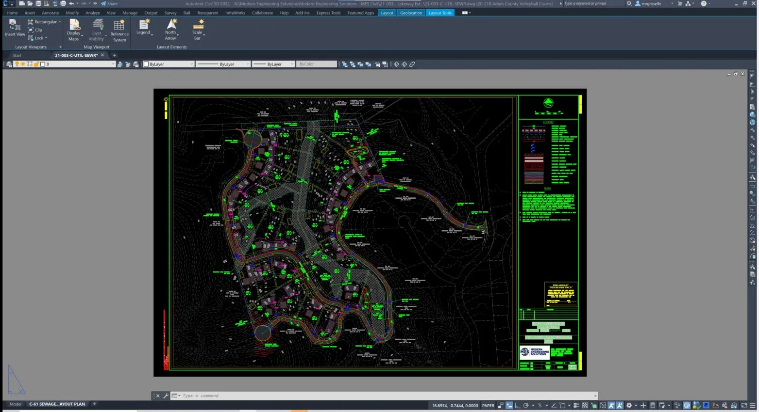
- Survey first. Bring the survey in as an external reference (xref) in the right coordinate system and units, and ask which foot the surveyor used. NIST's U.S. survey foot page says that foot became obsolete on January 1, 2023, replaced by the international foot of exactly 0.3048 meter. The two differ by about 2 parts per million, which matters on state plane coordinates in the millions of feet.
- Split the model. Keep survey, grading, yard piping and process units in separate files so two people can work at once. Autodesk's help on overlays notes the Overlay option excludes nested xrefs, so shared bases do not pile up inside each other.
- One layer standard. Use your firm's or the U.S. National CAD Standard, which includes the AIA CAD Layer Guidelines. Give raw sewage, RAS, WAS, air and potable water their own layers and linetypes.
- Blocks for equipment. Draw valves, pumps and manholes as blocks. AutoCAD's Count feature, per Autodesk's Count Blocks Quickly page, counts block instances in the drawing or an area, a fast check against the equipment schedule.
- Compare before you redraw. The XCOMPARE command compares an attached xref with the latest state of its source and marks differences in color inside revision clouds.
- Keep the file clean. Autodesk's guide to maintaining clean drawings pairs AUDIT, which checks the open drawing for errors, with PURGE, which removes unused data.
How do you draw the piping layout and show flow direction?
To scale, labeled, and with a flow arrow on every line.
- Draw pipe centerlines at true length and location, with bends and manholes, so gravity slopes can be checked.
- Label diameter and material on every run, and slope or inverts on gravity lines.
- Put flow arrows on influent, plant flow, RAS, WAS and effluent lines.
- Avoid crossings. Where pipes cross, break the lower line and note which passes under.
A note on limits: this is general education, not a design. It cites Texas and federal rules as of October 2026. Other states apply their own criteria, and your permit and engineer of record govern.
Frequently asked questions
Is a water treatment plant drawing different from a wastewater plant drawing?
The CAD practice is the same. The process and rules differ. In Texas, public water system design falls under 30 TAC Chapter 290, Subchapter D, where §290.42 covers water treatment, while domestic wastewater plants follow Chapter 217.
Does Chapter 217 cover industrial wastewater treatment plant design?
Not for wastewater that lacks the characteristics of domestic wastewater, even if it contains some. 30 TAC §217.1(a)(3)(B) excludes those systems. Industrial design starts with characterizing the actual waste stream.
I'm a civil designer in Texas drafting my first package plant site plan for a developer. What should be on it before the process engineer sends unit sizes?
Survey, property lines, easements, the incoming sewer and the likely outfall. Then the lines that limit where tanks go: the 150-foot §309.13 buffer offset, any water well setbacks in the same rule, and the 100-year flood plain if it is within 1,000 feet, per §217.35. Add a truck route to the headworks and sludge area. The process layout then drops into the space that is left.
I'm a utility engineer in Texas reviewing a consultant's plant drawings before they go to TCEQ. What should I check first?
Check the set against the §217.13(c)(2)(A) list, the seal on each sheet, the flood plain on the site plan and the FEMA 100-year water surface on the hydraulic profile. Then confirm the design flow matches the permit, since §217.32 ties one to the other.
Related resources
- The Civil Engineer’s Role in the Wastewater Treatment Process
- Flow Rate Projections: How to Size a Wastewater Treatment Plant for Your Development Without Over-Building
- Package WWTP vs. Custom-Designed Plant: Which One Fits Your Project?
- Public Water System Design and Implementation in Texas
Drawing a treatment plant set that has to pass review?
Modern Engineering Solutions is a civil engineering design firm licensed in nine states, working in water and wastewater engineering.
Headquarters in McKinney, Texas, with offices in Golden, Colorado and San Jose, California. Talk to our wastewater team or call (214) 833-6748.
Keep reading
More to read.
Talk to an engineer
Tell us about your project.
An engineer reads it
Not a salesperson. Someone who can tell you whether the pathway is real.
You get a first answer
Your options, the agencies involved and the questions that decide cost and schedule.
You decide
No commitment to have the first call.
Prefer the phone? (214) 833-6748