
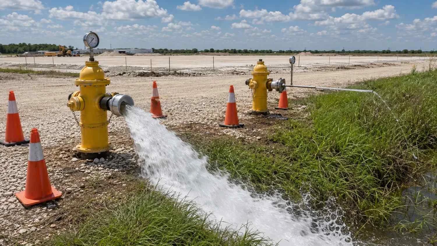
Blog
How to Conduct a Fire Flow Analysis for a Texas Development or Subdivision
A Texas fire flow analysis shows whether your water connection can deliver the fire flow your code requires at 20 psi, and what to do if it falls short.
A Texas fire flow analysis answers one question: can the water system at your connection deliver the flow your fire code official requires, for as long as it requires, while holding 20 psi of residual pressure? It takes four steps. Confirm the required flow, flow test the hydrants at your connection, model the system with your project added, and size the fix if it comes up short. Do it during feasibility, before the plat and the utility layout are fixed.
What does a fire flow analysis check?
It compares two numbers, both at 20 psi residual: the fire flow the code requires and the fire flow the system can deliver.
Appendix B of the 2021 International Fire Code, as Seattle publishes it with its local changes marked, defines fire flow as the flow available for fire fighting, measured at 20 psi residual pressure. A hydrant that delivers the gallons but drags the main below 20 psi fails. Texas draws the same line: a public water system intended to fight fires must be designed to hold 20 psi under combined fire and drinking water flow (30 TAC §290.44(d)).
Who sets the required fire flow for a Texas site?
The fire code official where the site sits, under the fire code that jurisdiction adopted. Appendix B applies only if the adopting ordinance references it.
Outside city limits it gets less clear. Only counties over 250,000 people and their neighbors may adopt a fire code, and it reaches only commercial buildings, public buildings and multifamily buildings of four or more units (Local Government Code §§233.061 and 233.062), and an emergency services district may adopt its own fire code (Health and Safety Code §775.036). A rural single-family subdivision may have no fire code target at all. Ask before you assume a number.
How much fire flow does Appendix B require?
From 500 gpm for a small sprinklered home to 8,000 gpm for a very large unsprinklered building, depending on use, construction type, floor area and sprinklers.
- One- and two-family homes up to 3,600 square feet: 1,000 gpm for one hour, or 500 gpm for half an hour with a residential sprinkler system (Table B105.1(1)).
- Other buildings: Table B105.1(2), by construction type and floor area. It starts at 1,500 gpm for two hours. From 3,000 gpm the duration is three hours, from 4,000 gpm four.
- An NFPA 13 sprinkler system cuts the table value to 25 percent, but not below 1,000 gpm (Table B105.2).
- Fire walls without openings can split a building into separate fire flow calculation areas (Section B104.2).
Several of those inputs are design choices the developer controls.
Does meeting TCEQ rules mean the system can deliver fire flow?
No. TCEQ's minimums are built around drinking water, not fire flow.
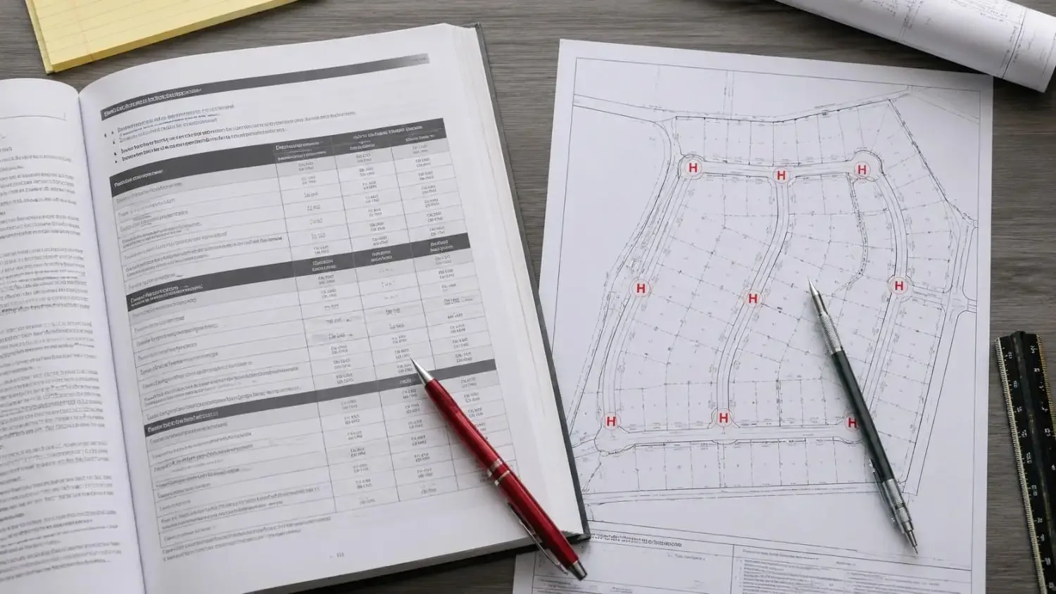
TCEQ's minimum waterline sizes "are for domestic flows only and do not consider fire flows" (§290.44(c)). Where 30 TAC §290.46(x) and (y) apply, in certain cities or by city ordinance, residential hydrants need at least 250 gpm for two hours at 20 psi, on top of maximum daily demand. That is a quarter of Appendix B's figure for one small unsprinklered house. A city ordinance under Health and Safety Code §341.0359 may not require a utility to build, retrofit or improve existing infrastructure. If the lines at your connection are too small, expect the upgrade to land on your project.
How do you run a hydrant flow test?
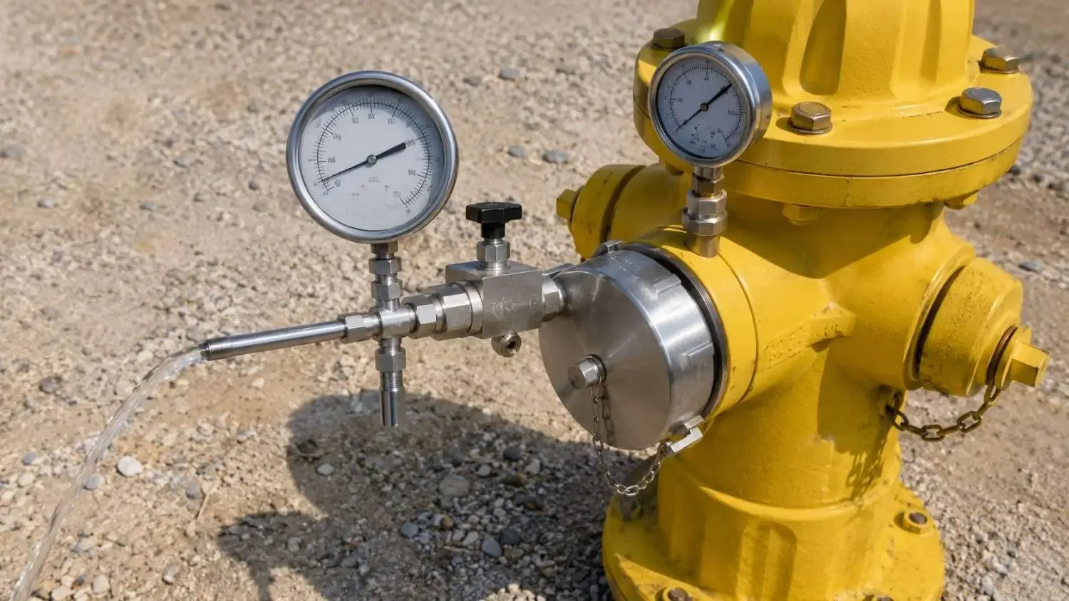
Using two hydrants near your connection, read static pressure at one, then its residual while the other flows, and project to 20 psi.
The University of Tennessee's MTAS guide to conducting a fire flow test lays it out: static pressure at the test hydrant closest to the property, then a pitot reading at the fully open flow hydrant while you read residual pressure. The guide quotes NFPA 291: flow enough to drop the residual hydrant's pressure at least 25 percent. Then project:
Q at 20 psi = Q test x ((static - 20) / (static - residual))^0.54
Say the test reads 60 psi static and 40 psi residual while flowing 800 gpm. That is a 33 percent drop, and it projects to about 1,163 gpm at 20 psi. Against a 1,500 gpm requirement, the site is short before your project adds any demand.
Test where you will connect. A hydrant on a different main or pressure zone tells you about that main.
Why do you still need a hydraulic model after the test?
The test shows one hydrant on one day. The model shows the system at maximum day demand, with your project added, at every new hydrant.
The EPANET 2.2 user manual warns that pipe roughness can change considerably with age, so calibrate older mains until the model matches the test. It also shows how an emitter computes the flow available at a junction at a minimum residual pressure. One trap: a demand-driven run delivers every demand, even at negative pressure. A hydrant showing full flow below zero psi has failed.
Write it up so the fire code official can check it. A water system model and fire flow memo for a rural project shows the format.
What fixes a fire flow shortfall?
Bigger or looped pipe, storage closer to the site, a booster pump station, or a lower required flow.
- Upsize the segment the model says controls. In EPANET's Hazen-Williams formula, head loss varies with diameter to the minus 4.871 power, so at the same flow a 6-inch to 8-inch upsize cuts friction loss to about a quarter.
- Loop dead ends so hydrants draw from two directions.
- Add storage near the site. 1,500 gpm for two hours is 180,000 gallons.
- Boost a site that sits high in its pressure zone.
- Lower the requirement with sprinklers or fire walls.
Where no adequate water system exists, Appendix B lets the fire code official use NFPA 1142 (Section B103.3), which sizes stored water in gallons. As Fresno County Fire's NFPA 1142 calculation guide shows, it is structure volume times a construction class number, divided by an occupancy hazard number, times 1.5 for an exposure within 50 feet. A 100 by 60 by 20 foot noncombustible store with no exposure: 120,000 cubic feet x 0.75 / 4 = 22,500 gallons.
When should a developer run the fire flow analysis?
During feasibility, before the plat, the site plan and the utility layout are fixed.
For developers and builders, timing decides how much the answer hurts. Found early, a shortfall is a line item. Found in plan review, it means a redesign, an unplanned offsite main or a delay. Put the hydrant test and a first model run in the site feasibility scope.
Are you ready to start a fire flow analysis?
Yes to all six means you can start. Each no is the first task.
- Do you know which fire code and edition govern the site, and whether Appendix B is adopted?
- Has the fire code official confirmed the required flow and duration in writing?
- Do you know each building's construction type, floor area and sprinkler plan?
- Has the water provider said where you can connect and whether it provides fire flow?
- Do you have a recent hydrant flow test near that connection?
- Can you get the provider's pipe sizes, tank levels and pump data?
Then ask your engineer which hydrant controls the result and what changes if a building gets sprinklers.
A note on limits: this is general education on the 2021 IFC Appendix B and the Texas rules cited, as of October 2026. Your adopted code, local amendments and fire code official decide what applies, and nothing here predicts a review outcome.
Frequently asked questions
Does every Texas development need a fire flow analysis?
You need one whenever a fire code official, city or water provider sets a fire flow target for your site. Outside cities, ask the county and any emergency services district.
What is fire flow?
The flow a water supply can deliver for fire fighting while holding 20 psi of residual pressure.
I'm developing a 60-lot subdivision outside city limits in Central Texas, and the water supply corporation says its lines were never built for fire flow. What are my options?
Believe them; Chapter 290's minimum line sizes ignore fire flow. First confirm whether any fire code target applies to the homes. If one does, the options are an upsized line from a point that can deliver the flow, storage and pumping the fire code official accepts, or NFPA 1142 storage.
I'm building a 30,000 square foot warehouse in North Texas, Type IIB construction, and the hydrant test came back short. Will sprinklers lower the fire flow I need?
Yes, often by a lot. Unsprinklered, Table B105.1(2) puts 30,000 square feet of Type IIB at 3,750 gpm for three hours. With an NFPA 13 system, Table B105.2 allows 25 percent, about 938 gpm, raised to the 1,000 gpm floor. The supply must still cover the greater of that flow or the sprinkler demand with hose stream (Section B105.3).
Related resources
- Fire Flow Analysis: Engineering Solutions for Municipal Water Distribution Systems
- What a Utility Feasibility Study Actually Tells You, and When to Get One
- Why EPANET Is the First Choice for Water Network Modeling
- How to Read a Hydraulic Grade Line
Not sure your connection can carry fire flow?
We coordinate the hydrant test, build and calibrate the model, and size the fix before your plat goes in, so plan review does not find the shortfall for you.
Modern Engineering Solutions, McKinney, Texas. 525+ projects completed. Call (214) 833-6748.
Keep reading
More to read.
Talk to an engineer
Tell us about your project.
An engineer reads it
Not a salesperson. Someone who can tell you whether the pathway is real.
You get a first answer
Your options, the agencies involved and the questions that decide cost and schedule.
You decide
No commitment to have the first call.
Prefer the phone? (214) 833-6748