
Blog
Lift Station Design for Florida’s Flat Topography: Challenges Every Developer Should Understand
Florida lift station design starts with flat ground and a high water table. See FDEP rules on backup power, flotation and floods, and what to settle first.
Florida lift station design starts with the ground. On a flat site, a gravity sewer has to keep falling to keep flowing, so it gets deeper with every foot until it runs into the water table, and from there a pump is the practical way forward. The stations that work are placed from a sewer profile, sized for buildout, built to resist flotation and kept running through a storm.
Why do flat Florida sites need so many lift stations?
Because a gravity sewer needs slope, and on flat ground every foot of slope becomes a foot of depth.
The Recommended Standards for Wastewater Facilities, 2014 edition, usually called the Ten States Standards, recommends a minimum slope of 0.40 feet per 100 feet for an 8-inch sewer, and at least 2.0 feet per second flowing full. FDEP lists the document as design guidance in Rule 62-604.300, F.A.C. It is guidance, not rule text, and your utility may set its own numbers.
At that slope, an 8-inch main drops 8 feet in 2,000 feet. Start the first manhole 5 feet deep on level ground and the invert ends 13 feet down. If the seasonal high water table is 3 feet below grade, the whole trench bottom sits below it, so the full run needs dewatering and trench support.
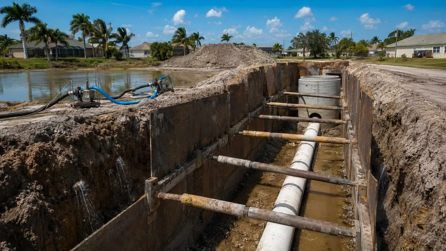
A station goes where one more foot of depth causes more trouble than a pump. The sewer profile sets the number and location of stations, not a rule of thumb.
How do you size the wet well and pick the pumps?
Size the wet well for fill time and cycling. Pick pumps that carry peak hourly flow with any one unit out of service.
The Ten States Standards base the wet well's effective volume on design average flow and a fill time of no more than 30 minutes, unless the station is designed for flow equalization, with the minimum cycle time from the pump maker (Section 42.62). Too small, and the pumps short cycle. Too large, and the wastewater sits, turns septic and makes hydrogen sulfide.
Section 42.31 calls for multiple pumps, the same size when there are only two, able to handle design peak hourly flow with any unit out of service. Section 42.4 calls for automatic alternation. Then check the pump curve against the system curve at minimum, average and peak flow. Our walkthrough of force main and pump sizing calculations shows the steps.
How does a high water table change the structure?
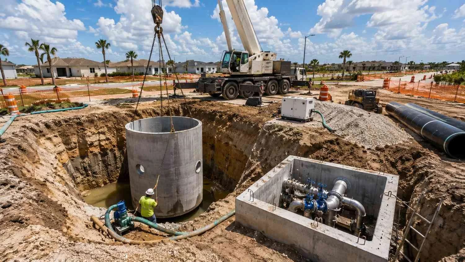
An empty wet well in saturated ground wants to float, and Florida's rule makes you design for it.
Rule 62-604.400, F.A.C., paragraph (2)(e), says a pump station in an area with a high water table must be designed to withstand flotation forces when empty. Uplift equals the weight of the water displaced. Resist it with the structure's weight, an extended base slab that picks up soil, added concrete or anchors. Check it with groundwater at its highest expected level and the wet well empty, during construction too.
The same paragraph requires the electrical and mechanical equipment to be protected from the 100-year flood and the station to stay operational and accessible in the 25-year flood, or a lower flood that local conditions justify, never below the 10-year.
Corrosion is the other load. EPA's CMOM guide for collection systems explains that hydrogen sulfide forms sulfuric acid on exposed surfaces, which corrodes concrete and ferrous metals. The Ten States Standards ask for materials suited to it (Section 42.25).
What standby power does FDEP require at a lift station?
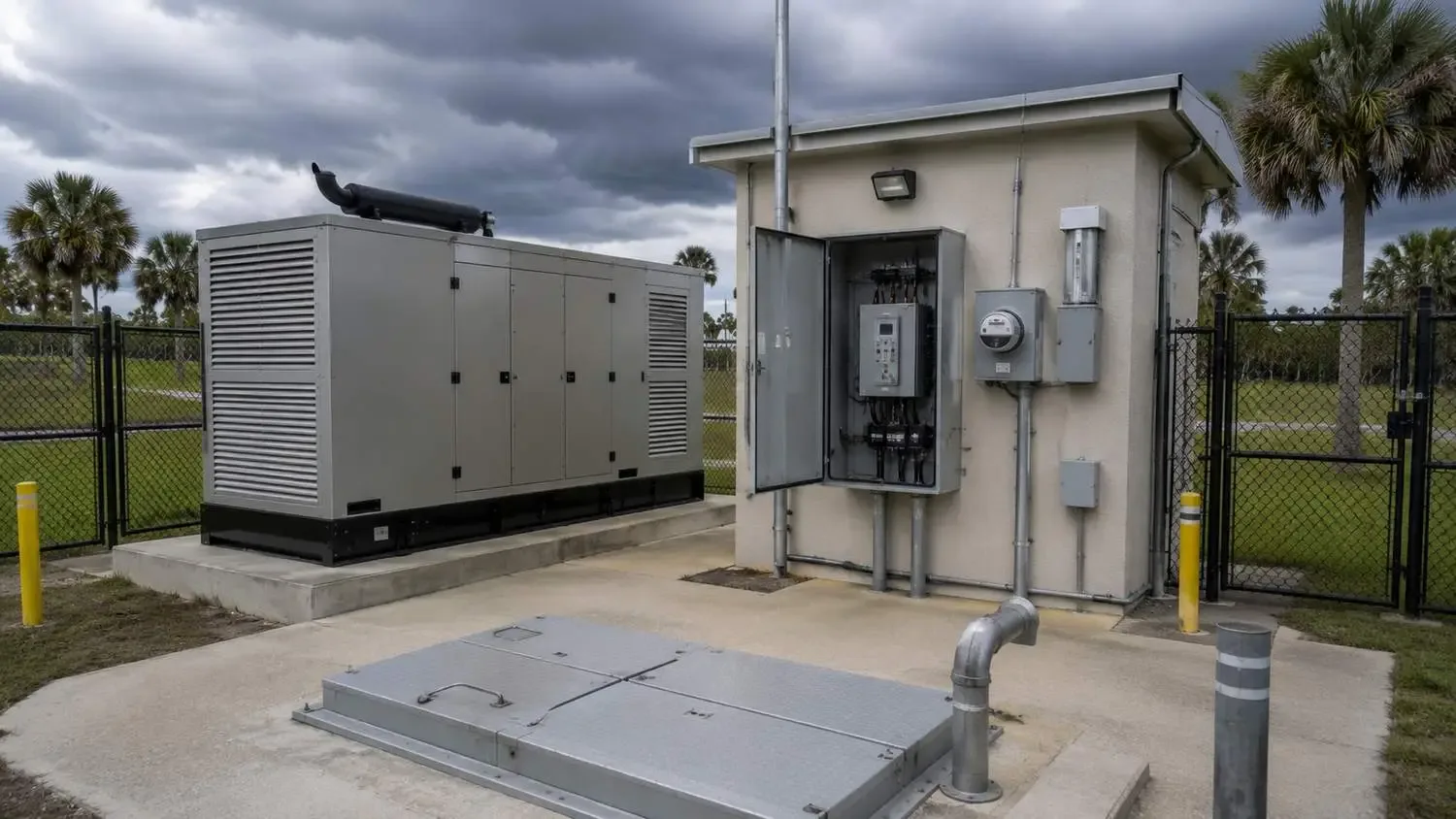
Every pump station needs emergency pumping capability. Some need an in-place generator.
Rule 62-604.400(2)(a) sets the split:
- A station that receives flow from another station through a force main, or discharges through pipe 12 inches or larger, needs an in-place emergency generator.
- Any other station can use two independent utility substations, a generator connection or portable pumps.
- Every station gets a force main riser with rapid connections for a portable pump, and the backup must run the station's total rated capacity.
The backup must also be compatible with the operator's temporary generators and pumps. In a regional outage, that portable unit may be headed to someone else's station. That is the case for an in-place generator even where a hookup is allowed.
Storage buys time: the volume between the high-level alarm and the lowest overflow point, divided by inflow. If a spill happens, Rule 62-604.550, F.A.C. requires an oral report within 24 hours, to the State Watch Office when it tops 1,000 gallons or endangers health or the environment, and a written report within five days unless FDEP waives it.
How should you route the force main and control odor?
Keep it moving at 2 feet per second or more, vent the high points and keep detention short.
The Ten States Standards recommend at least 2 and no more than 8 feet per second at design pumping rates, with a 4-inch minimum diameter (Section 49.1), and air relief valves at high points (Section 49.2). Each valve is a maintenance point that needs access.
The EPA guide lists pump stations, sewers with long detention times and force main discharge points among the areas where hydrogen sulfide forms. Rule 62-604.400(2)(c) requires new stations to be designed and sited to minimize odor, noise and lighting effects on neighbors, using tools such as buffers, chemical addition and treatment of vented gases.
How much room does a lift station site need?
Enough for a truck in any weather, equipment to pull pumps, and a fence and sign.
Rule 62-604.400(1)(b) puts the system on public right-of-way, the permittee's land or easements, and (2)(d) requires a fence or similar barrier and a sign with an emergency phone number. The Ten States Standards want all-weather access for maintenance vehicles (Section 41.2). For developers and builders, the station tract and access drive belong on the first concept plan.
What FDEP permit does a new lift station need?
A conventional station can usually go under FDEP's general permit, with notice at least 30 days before construction.
Rule 62-604.600, F.A.C., subsection (6), grants it for systems designed to Rule 62-604.400 when, among other conditions, the receiving plant has capacity for your flow. Confirm that capacity in a site feasibility study before you close on the land.
Is your site ready for lift station design?
Six yeses mean it is ready. Any no is the next thing to settle.
- Do you have a gravity sewer profile for the whole site?
- Do you know the seasonal high water table at each likely station site?
- Do you have the accepting utility's lift station standards in writing?
- Is the design flow based on full buildout, with initial flows checked?
- Do you know which stations need an in-place generator?
- Has the receiving plant confirmed capacity for your flow?
Ask your engineer: Where does the sewer profile cross the water table? Which station hurts most if the power fails?
A note on limits: this is general education from Florida rules and the 2014 Ten States Standards as of October 2026. Your utility's standards and your permit govern, and no article can predict a review outcome or schedule.
Frequently asked questions
Can a gravity sewer run flatter than the minimum slope?
Sometimes. The Ten States Standards allow slightly flatter slopes where flow depth reaches 0.3 of the diameter at design average flow and the operating authority commits in writing to the extra maintenance (Section 33.42). An oversized pipe does not justify a flatter slope (Section 33.43).
Does every Florida lift station need a generator?
No. Every station needs emergency pumping capability, but only the stations named in Rule 62-604.400(2)(a)1 must have one in place. Paragraph (2)(b) adds power generation for complex or critical stations.
I'm developing a 300-lot subdivision on flat land near the Florida coast, and the civil plan shows three lift stations. How do I know whether that number makes sense?
Ask for the sewer profile behind them. Each station should sit where the next run would go too deep for the water table and soils. Long runs below the seasonal high water table, or a station in a low spot that floods, are reasons to push back.
I'm a developer in Central Florida, and the county utility will own our lift stations. What should I get from them before design starts?
Their written lift station standards: pumps, control panel, telemetry, generator or hookup, and tract size. The backup has to work with their equipment, so their fleet sets part of the design.
We're building phase one of a four-phase Florida community. Should the first lift station be sized for buildout or for phase one?
Usually both: the wet well for buildout, pumps staged. The Ten States Standards want the 30-minute fill time met at initial flows too. A later capacity upgrade is a modification that generally needs a permit under Rule 62-604.600.
Related resources
- FDEP Permitting for Wastewater Systems in Florida: A Practical Guide for Developers
- Force Main Corrosion in Florida’s Coastal Environment: Design Strategies That Last
- Gravity Sewer vs. Pressure Sewer: Choosing the Right System for Your Community
- Lift Stations and Collection Systems: What the Plant Needs Upstream to Function Properly
Planning lift stations for a flat Florida site?
We lay the gravity sewer against the water table first, then place and size the stations to FDEP rules and your utility's standards.
Modern Engineering Solutions, McKinney, Texas. Licensed in Florida.
Talk to an engineer about your site or call (214) 833-6748.
Keep reading
More to read.
Talk to an engineer
Tell us about your project.
An engineer reads it
Not a salesperson. Someone who can tell you whether the pathway is real.
You get a first answer
Your options, the agencies involved and the questions that decide cost and schedule.
You decide
No commitment to have the first call.
Prefer the phone? (214) 833-6748