
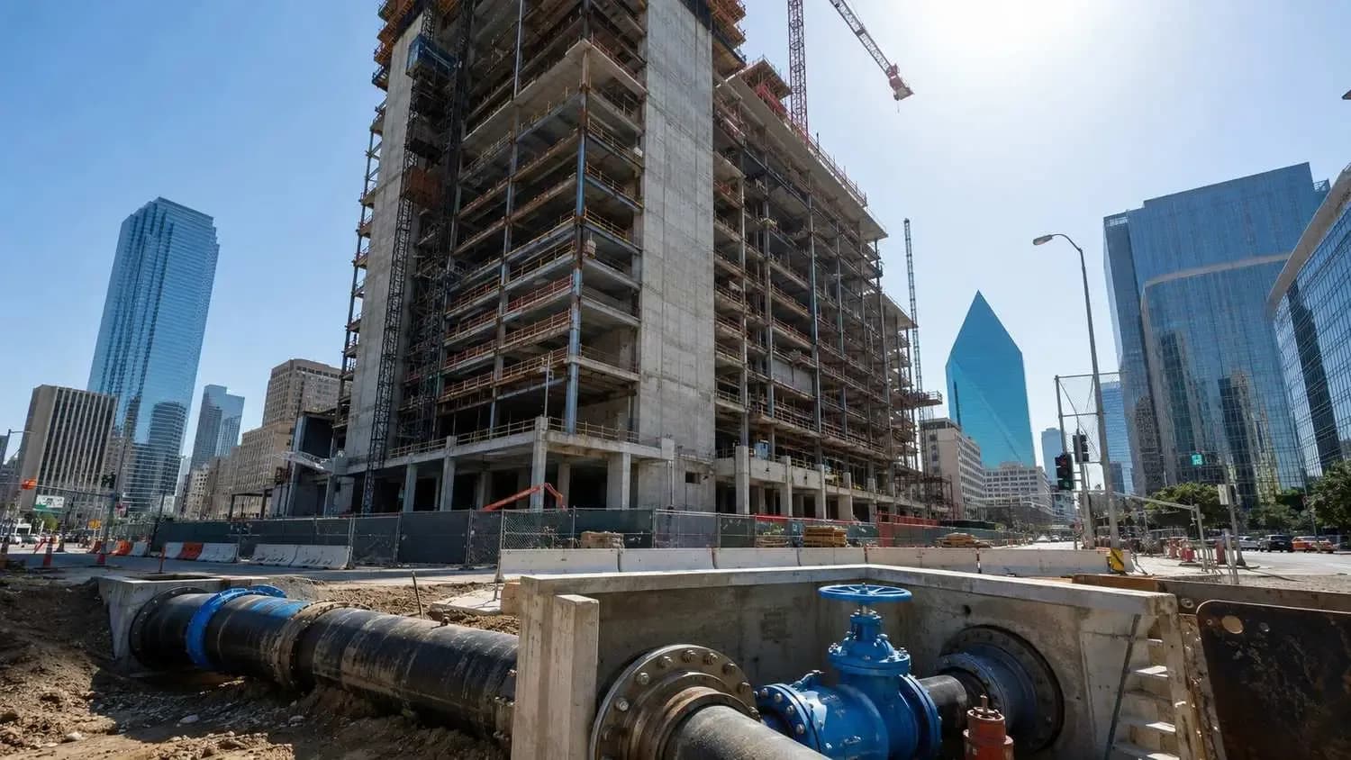
Blog
Hydraulic Modeling for Dallas High Rise Developments: Why Pressure Zone Design Matters More Than You Think
Pressure zone design failures stop Dallas high rise permits cold. Learn why hydraulic modeling before schematic design protects your schedule and budget.
Quick Answer
Pressure zone design for a Dallas high rise or dense urban development determines whether the domestic water demand and fire flow requirements of the building can actually be delivered by the municipal water system at the pressures the building’s plumbing and fire protection systems require at every floor. Hydraulic modeling of the existing distribution system, combined with hydrant flow testing at the specific project site, establishes the available pressure and flow at the point of connection under both normal and fire flow conditions. When that available pressure is insufficient for the building’s upper floors, which is common for buildings above roughly six to eight stories connecting to a typical municipal system, the project requires booster pump stations, pressure reducing valve vaults, or intermediate storage that must be sized and located correctly in the earliest design phase. Projects that model hydraulic conditions before finalizing architectural and MEP design avoid the redesign, cost increase, and schedule delay that come from discovering a pressure deficiency after construction documents are already substantially complete.
Why Pressure Zone Design Is a Bigger Deal in Dense Urban Development Than Most Teams Expect
Municipal water distribution systems are designed to deliver adequate pressure and flow to the range of building types anticipated in a given service area, and in most of the Dallas area outside the downtown urban core, that design assumption is built around low rise residential and commercial construction. A municipal system delivering 60 to 80 psi of static pressure at street level performs that job well for a two story retail building or a garden style apartment complex. The same system, delivering the same pressure at the same point of connection, may be entirely inadequate for a fifteen story residential tower where the plumbing code requires a minimum residual pressure at the highest fixture and the fire protection system requires a specific residual pressure at the highest standpipe outlet under flowing conditions.
The physics driving this gap is straightforward but frequently underestimated in early design assumptions. Water pressure decreases by approximately 0.433 psi for every foot of elevation gain. A building with floor to floor heights of roughly twelve feet loses approximately 5.2 psi of static pressure for every floor above street level, before accounting for any friction loss in the building’s internal piping or any velocity pressure required at the fixture. A twenty story building has approximately 240 feet of elevation from street level to the top floor, which alone consumes over 100 psi of the available system pressure just to reach that elevation, without yet accounting for the pressure required to actually operate a fixture or supply a fire protection system once the water arrives.
This is why a project team that assumes municipal water pressure is “probably fine” because a neighboring low rise building down the street has functioned without complaint is making an assumption that does not transfer to a high rise building on the same water main. The municipal system’s available pressure at the point of connection is a fixed physical quantity determined by the system’s design and current operating condition, and how far that pressure can push water upward through a building is a hydraulic calculation, not an assumption, and it needs to be performed for the specific building height and configuration proposed.
Domestic Demand, Fire Flow, and Why They Are Different Hydraulic Problems
Domestic water demand and fire flow demand for a high rise building are governed by different code requirements, occur under different operating conditions, and in many cases drive different design solutions, which is why a hydraulic evaluation for a dense urban project needs to address both explicitly rather than assuming that solving one automatically solves the other. Domestic demand analysis establishes the peak instantaneous flow rate the building’s plumbing fixtures will require under normal operating conditions, calculated using fixture unit methods from the applicable plumbing code, and the minimum residual pressure that must be maintained at the highest and most hydraulically remote fixture in the building under that peak demand condition.
Fire flow demand analysis establishes the flow rate and residual pressure the fire protection system requires at the base of the standpipe or at the fire department connection under a fire flow condition, which is a substantially higher flow rate sustained for a defined duration, evaluated according to the applicable fire code and the specific fire protection system design, whether that is a standpipe system, an automatic sprinkler system, or both. For a high-rise building, the fire protection system’s residual pressure requirement at the highest floor, combined with the friction loss through the standpipe riser and the elevation loss to reach that floor, frequently establishes a higher total pressure requirement at the base of the building than the domestic demand condition does, which means the fire flow condition is often the governing case that determines whether a booster pump system is required and how it must be sized.
Because these two demand conditions are evaluated separately and can drive different equipment requirements, a hydraulic model prepared for a high rise project should explicitly present both the domestic demand scenario and the fire flow scenario, at the specific point of connection to the municipal system, using pressure and flow data obtained from an actual hydrant flow test at or near the project site rather than from published system design values that may not reflect current system performance.
Hydrant Flow Testing and Why Modeled Assumptions Are Not Enough
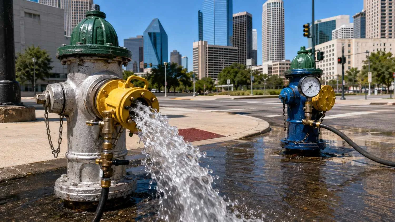
A hydrant flow test performed at or near the project site is the foundation of a credible hydraulic analysis for a high rise project, because it measures the actual current performance of the municipal system at that location rather than relying on the system’s original design specifications, which, as discussed in the context of aging water infrastructure in Dallas, can diverge significantly from actual field performance due to pipe age, internal corrosion, and changes in system operation since original design. A flow test measures static pressure, the pressure in the system under no-flow conditions, and residual pressure and flow at a specified flow rate, typically obtained by opening a nearby hydrant and measuring the pressure drop at a test hydrant while the flow hydrant is open.
The flow test data is then used to calculate the system’s available flow at any target residual pressure using standard hydraulic formulas, which allows the engineer to determine, for example, what flow the system can deliver at the specific residual pressure the fire protection system requires at the point of connection. This calculated available flow, compared against the building’s actual fire flow demand established by the fire protection engineer, determines whether the municipal system alone can satisfy the building’s requirement or whether supplemental infrastructure, a fire pump, a booster pump station, or onsite storage, is needed to close the gap.
Performing this flow test and hydraulic analysis during early design, ideally during schematic design before the building’s fire protection and domestic water system approach is finalized, allows the project team to make informed decisions about building system design with accurate information about what the municipal system can actually deliver. Performing the same analysis after construction documents are complete, when a plan reviewer or the fire marshal requests it as part of permit review, converts a design input into a redesign trigger, with all the cost and schedule consequences that implies.
Booster Pump Stations, PRV Vaults, and Storage Coordination
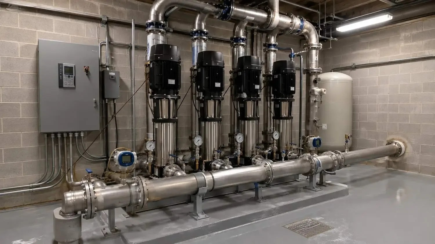
When a hydraulic analysis determines that the municipal system cannot deliver adequate pressure and flow at the building’s upper floors under either the domestic or fire flow condition, a booster pump station is the most common solution for high rise projects. A booster pump station is sized based on the specific flow and pressure deficit identified in the hydraulic analysis, and its design must account for the range of operating conditions the building will experience, from low flow domestic demand during off peak hours to peak domestic demand during morning and evening use patterns to the fire flow condition that represents the system’s maximum design flow requirement, even though that condition may occur rarely if ever during the building’s actual operating life.
Booster pump station location and space allocation is a coordination point between civil engineering and building architecture that needs to be resolved early, because the pump station requires dedicated mechanical space, often in a basement or ground floor mechanical room, with adequate access for installation and maintenance, adequate electrical service, and in many cases backup power provisions given the life-safety implications of fire protection system reliability. A pump station location decided after the building’s mechanical spaces have already been allocated for other equipment is a common source of late stage design conflict.
Pressure reducing valve vaults serve the opposite function from booster pumps, reducing excessive pressure to a safe operating range, and are relevant in high rise design when a building’s lower floors would otherwise experience pressure exceeding the maximum allowable working pressure for plumbing fixtures and piping due to the combination of high municipal system pressure and minimal elevation loss at those lower floors. Buildings with a wide range of floor elevations, from below grade parking to a top floor forty or fifty stories above street level, frequently require multiple pressure zones internally, each served by its own PRV arrangement, to keep pressure within an acceptable range throughout the building rather than accepting excessive pressure at the lowest floors to ensure adequate pressure at the highest.
Storage coordination, whether through a fire protection water storage tank, a domestic water storage and repump system, or coordination with the municipal system’s existing storage infrastructure, is a related design element that affects both the reliability of the building’s water supply during peak demand or fire conditions and the sizing requirements for booster pump equipment. A hydraulic analysis that identifies a storage component as part of the recommended solution should evaluate the specific storage volume required based on the demand scenario driving the need, not an arbitrary storage allowance that may be significantly oversized or undersized relative to the actual requirement.
Coordination Between Civil Engineering, MEP, and Municipal Reviewers
The hydraulic modeling and pressure zone design process for a Dallas high rise project is inherently a coordination exercise between the civil engineer, who evaluates the municipal system’s capacity and the point of connection conditions, the MEP engineer, who designs the building’s internal domestic water distribution and coordinates with the fire protection engineer on standpipe and sprinkler system design, and the municipal plan reviewer and fire marshal, who ultimately approve the design against the applicable code requirements. A hydraulic analysis performed in isolation by the civil engineer without coordination with the MEP and fire protection design team produces a system capacity assessment that may not align with the actual demand the building systems will place on it. An MEP design developed without input on the actual available municipal system pressure produces a building system design based on assumptions that field verification may later disprove.
Early coordination among these three parties, ideally beginning during schematic design with a flow test and preliminary hydraulic analysis informing the building system design approach from the outset, is the practical mechanism that prevents the late stage review comment scenario that derails project schedules. Municipal reviewers in Dallas area jurisdictions are generally receptive to pre application meetings where a project team can present preliminary hydraulic findings and confirm the reviewer’s expectations for booster pump, PRV, or storage design before those systems are finalized in construction documents, and this pre application engagement is a schedule protection tool that is underused relative to its value.
Frequently Asked Questions
How early in the design process should we perform a hydrant flow test for a Dallas high rise project?
The flow test and preliminary hydraulic analysis should be performed during schematic design, before the fire protection and domestic water system approach is finalized in design development. This timing allows the results to inform the building system design, including whether a booster pump station or PRV vaults are needed, their approximate sizing, and the mechanical space allocation required for them, before those decisions are locked into the architectural floor plans. Waiting until construction documents are underway to perform the flow test risks discovering a pressure deficiency after mechanical space has already been allocated for other purposes, which is a significantly more expensive redesign scenario than addressing it during schematic design.
Our project site is served by a water main that appears adequate based on the municipality’s published system data. Do we still need a site specific flow test?
Yes. Published system design data reflects the system’s original design capacity, not necessarily its current field performance, which can be affected by pipe age, internal corrosion, current demand from other users on the same system, and changes in system operation since the original design was completed. A site specific flow test measures actual current conditions at the specific point of connection your project will use, which is the only reliable basis for a hydraulic analysis that will support a fire marshal or plan review submission. Relying on published design data without field verification is a common source of hydraulic analyses that do not hold up under review scrutiny.
What is the typical cost and schedule impact of adding a booster pump station to a high rise project’s design?
The cost and schedule impact depends on the specific flow and pressure deficit identified, the booster pump system configuration required, and how early in the design process the requirement is identified. A booster pump station requirement identified during schematic design can typically be integrated into the mechanical space planning and construction schedule with modest incremental cost and no schedule impact to the overall project. The same requirement identified during permit review, after construction documents are complete and mechanical spaces are allocated, typically requires design revisions to accommodate the pump station’s space and electrical requirements, which can add weeks to months to the design and permitting schedule depending on how much redesign is required. This difference in impact is the central reason early hydraulic evaluation is worth the modest upfront engineering investment.
Related Resources
- Water Line Replacement in Dallas: How Developers Navigate Aging Trinity River Authority Infrastructure
- Dallas Subdivision Wastewater Planning: When City Sewer Isn’t an Option in ETJ Growth Areas
- Land Application Permits in Texas: A Faster Path to Wastewater Approval for Developers
- Approved Plans Aren’t Always Optimized Plans: The Difference Can Cost $15 Million
- Biosolids Land Application from Private Wastewater Treatment Facilities in Texas
- TCEQ Permit Timelines for Dallas Area Industrial Facilities: What Food & Beverage Manufacturers Need to Know
Evaluating Water Pressure and Fire Flow Conditions for a Dallas High Rise or Dense Urban Project?
MES works with Dallas area developers, architects, MEP teams, and project managers to perform hydraulic modeling and pressure zone analysis, conduct hydrant flow testing, evaluate domestic and fire flow demand scenarios, design booster pump stations and PRV vaults, and coordinate with municipal reviewers and fire marshals before pressure assumptions become expensive late stage redesign problems.
We specialize in:
- Hydrant flow testing and hydraulic modeling for Dallas high rise, mixed use, and dense urban development projects
- Domestic demand and fire flow analysis for buildings requiring multi story pressure zone evaluation
- Booster pump station sizing, location coordination, and mechanical space planning for high rise water systems
- Pressure reducing valve vault design and internal building pressure zone coordination for tall structures
- Pre application coordination with Dallas area municipal water utilities and fire marshals for high rise water system approval
- Civil and MEP coordination support for water distribution design on dense urban and high rise development projects
Modern Engineering Solutions, Dallas, Texas. Contact: (214) 833-6748 or mod-eng.com
Keep reading
More to read.
Talk to an engineer
Tell us about your project.
An engineer reads it
Not a salesperson. Someone who can tell you whether the pathway is real.
You get a first answer
Your options, the agencies involved and the questions that decide cost and schedule.
You decide
No commitment to have the first call.
Prefer the phone? (214) 833-6748