
Blog
Reactive Clay Soils and Buried Utility Design: Engineering Water and Sewer Lines on Eagle Ford and Austin Chalk Formations
Eagle Ford and Austin Chalk reactive clay soils stress buried water and sewer lines for decades. Learn what design changes prevent costly post-construction failures.
Quick Answer
Reactive clay soils on Eagle Ford and Austin Chalk formations, common throughout significant portions of the Dallas area, undergo meaningful volume change as moisture content fluctuates, expanding when wet and shrinking when dry, and this shrink swell behavior exerts stress on buried water and sewer infrastructure that standard trench design assumptions, developed for more stable soil conditions, don’t adequately address. Left unaddressed, this soil movement contributes to pipe joint deflection and leakage, sewer line slope disruption that reduces flow capacity and increases infiltration, manhole settlement, water main stress that can lead to breaks, and pavement failures above utility trenches as the underlying soil movement transmits upward. Addressing these risks requires pipe material selection, bedding and backfill design, trench depth, and joint design that specifically account for the site’s actual geotechnical conditions, based on project specific geotechnical investigation rather than generic regional assumptions, and this coordination between geotechnical findings and utility design needs to happen during design, not as a repair response after the infrastructure has already failed.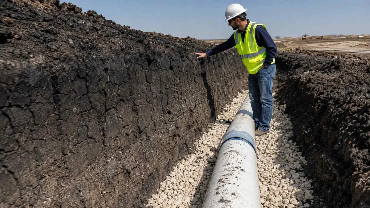
Why Eagle Ford and Austin Chalk Formations Create a Specific Utility Design Challenge
The geology underlying much of the Dallas area includes significant expanses of Eagle Ford Shale and Austin Chalk formations, both of which weather into clay rich soils with pronounced shrink swell behavior, meaning the soil’s volume changes measurably as its moisture content changes with seasonal rainfall and drought cycles. This isn’t a uniform condition across every Dallas-area site, since specific soil characteristics vary based on the underlying formation, depth to bedrock, and local weathering history, but reactive clay behavior is common enough across the region that it should be treated as a default design consideration for buried utility work rather than an exception addressed only when unusually severe soil conditions are suspected.
The practical consequence for buried infrastructure is that a pipe trench excavated through reactive clay, backfilled, and left in service experiences ongoing soil movement around and beneath the pipe as the surrounding clay continues its seasonal expansion and contraction cycle for as long as the pipe remains in service, which for water and sewer infrastructure is generally intended to be many decades. A trench and bedding design that doesn’t specifically account for this ongoing movement is essentially betting that the pipe, its joints, and its bedding will simply tolerate whatever stress the moving soil applies, a bet that sometimes pays off for a while but that tends to produce accumulating problems, joint leakage, pipe deflection, and eventual failure, well before the infrastructure’s intended service life is reached.
Buried Utilities as an Engineering Discipline, Not Just a Site Layout Exercise
It’s tempting to treat water and sewer line placement primarily as a civil site layout exercise, determining route, depth, and connection points, with the pipe material and installation details treated as relatively standardized specifications applied uniformly regardless of the specific site’s soil conditions. This approach works reasonably well in stable soil conditions where the standard specifications were originally developed with reasonably representative soil behavior in mind. It works considerably less well on reactive clay formations, where the standard specification’s underlying soil behavior assumptions don’t match the site’s actual conditions, and applying a standard trench and bedding design without adjustment for the site’s specific reactive clay behavior effectively installs infrastructure designed for different soil than the infrastructure will actually experience.
Buried utility design on reactive clay formations needs the same kind of site specific engineering attention that structural foundation design already routinely receives on these formations, since the same shrink swell behavior that requires specific foundation design considerations for buildings applies with equal force to buried pipe infrastructure, even though utility design doesn’t always receive the same level of geotechnical scrutiny that building foundation design does on the same site.
Pipe Material Selection for Reactive Clay Conditions
Different pipe materials respond differently to the stress reactive clay soil movement imposes, and material selection should specifically account for this rather than defaulting to whatever material a project team has used most commonly on other sites without regard for those other sites’ soil conditions. Flexible pipe materials, which can accommodate a degree of soil movement through controlled deflection without failure, behave differently under reactive clay stress than rigid pipe materials, which resist deformation but can be more prone to cracking if soil movement imposes stress beyond what the rigid material can absorb without deforming.
Neither flexible nor rigid pipe material is universally correct for reactive clay conditions, since the right choice depends on the specific application, water main versus sewer line, the specific soil conditions at the project site as identified through geotechnical investigation, and the specific joint and bedding design paired with whichever pipe material is selected. This decision should be made based on the project’s actual geotechnical findings and the specific application’s requirements, not on a blanket assumption that one pipe material category is always the correct choice for reactive clay sites generally.
Bedding and Backfill Design as the Primary Control Measure
Pipe bedding and backfill design is where reactive clay’s practical effects on buried utilities are most directly addressed, since properly designed bedding material and compaction can provide a more stable, uniform support condition for the pipe than simply backfilling the trench with the native reactive clay material that was excavated to create it. Using an imported bedding material with more stable, predictable behavior than native reactive clay, properly compacted to provide uniform pipe support, reduces the differential movement risk that occurs when a pipe rests partly on well compacted material and partly on soil that’s actively expanding or contracting beneath it. Backfill design above the bedding zone also deserves specific attention on reactive clay sites, since backfill material and compaction affect how much of the surrounding native soil’s shrink swell behavior actually transmits down to the pipe zone versus being absorbed or moderated by the backfill material’s own characteristics. Geotechnical recommendations specific to the project site should directly inform both the bedding and backfill material selection and the compaction requirements specified for the utility trench, rather than relying on a generic regional standard that doesn’t reflect the specific site’s actual soil investigation findings.Joint Deflection and Trench Depth Considerations
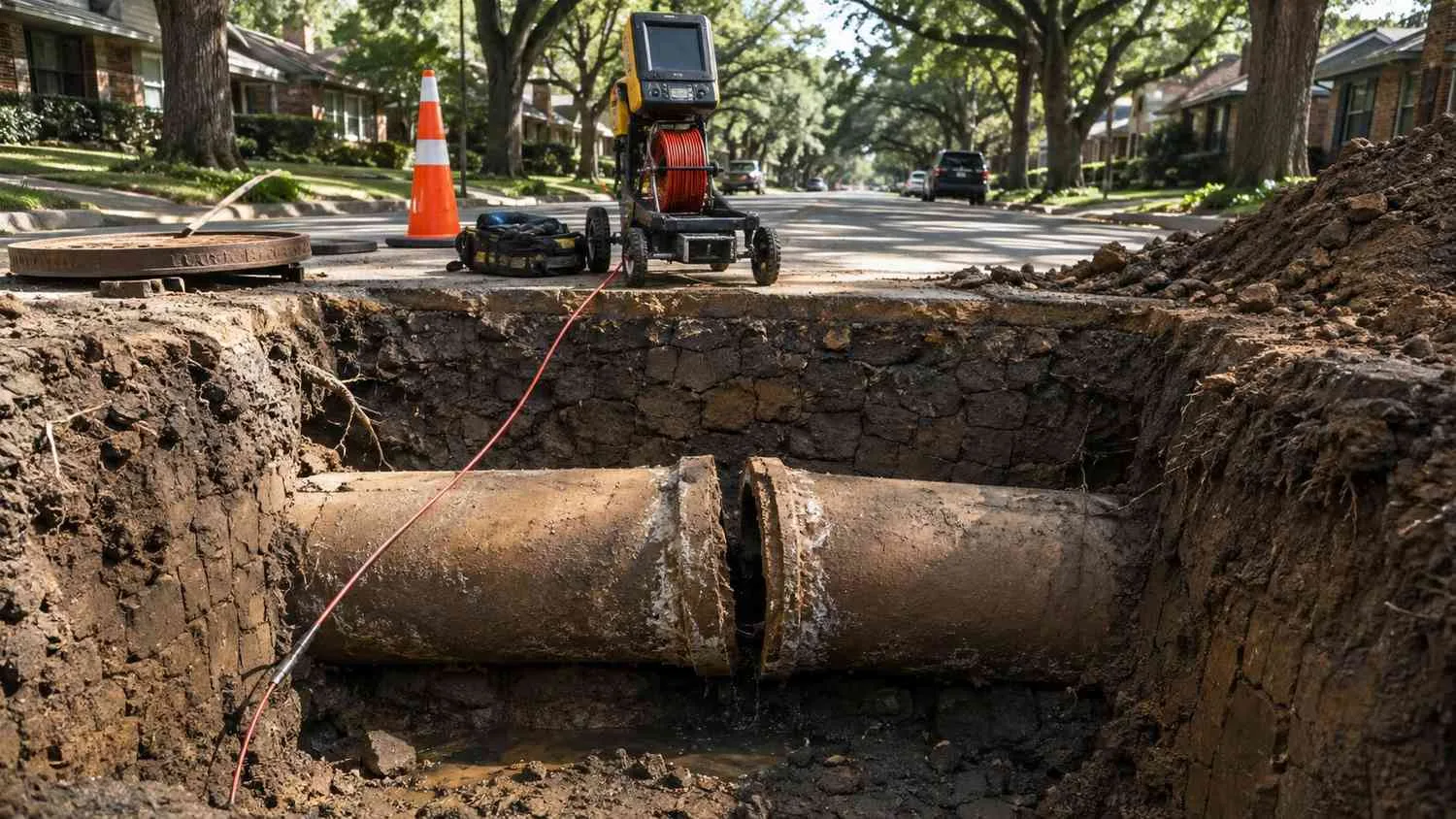
Pipe joints are frequently the specific location where reactive clay soil movement first manifests as a visible problem, since a joint that’s designed to accommodate some degree of deflection under normal installation tolerances can be pushed beyond its designed deflection range by ongoing soil movement, leading to leakage at the joint, which for a water main means water loss and potential main break risk, and for a sewer line means both potential exfiltration of wastewater into the surrounding soil and, more commonly identified as a problem, infiltration of groundwater into the sewer line through the same compromised joint.
Trench depth interacts with this joint deflection risk in a somewhat counterintuitive way, since deeper trenches, while sometimes necessary for other design reasons including maintaining adequate sewer slope or avoiding conflicts with other utilities, can place the pipe within a soil zone that experiences more pronounced seasonal moisture and therefore volume change than a shallower trench might, depending on the site’s specific soil moisture profile with depth. Evaluating trench depth’s interaction with the site’s specific reactive clay behavior at different depths, rather than assuming shallower is always better or deeper is always safer, requires the same site specific geotechnical input relevant to bedding and backfill design.
Sewer Slope Protection and Manhole Settlement
Gravity sewer lines depend on maintaining designed slope to convey flow reliably, and reactive clay soil movement that causes differential settlement or heaving along a sewer line’s length can disrupt that designed slope, creating low spots that accumulate solids and reduce flow capacity, or in more severe cases creating a slope reversal that causes standing wastewater and accelerated pipe deterioration at the affected location. This slope disruption risk is a specific reason why bedding and backfill design deserves particular attention for gravity sewer lines on reactive clay formations, since maintaining uniform, stable pipe support along the line’s entire length is directly connected to maintaining the designed slope over the system’s operating life.
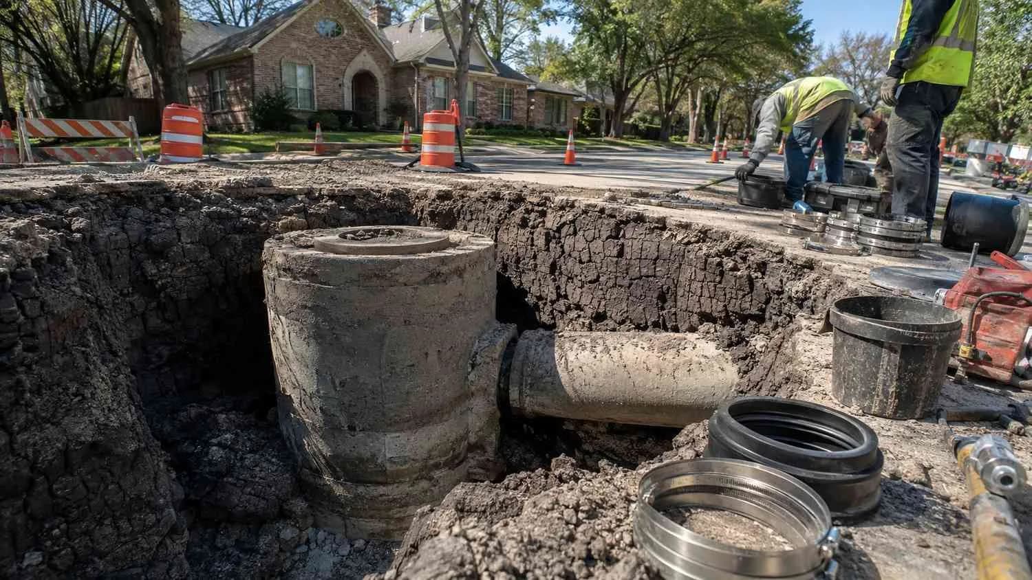
Manholes, as more massive, less flexible structures than the pipe itself, respond differently to reactive clay movement than the pipe does, and differential settlement between a manhole structure and the connecting pipe can create a specific stress concentration at the pipe to manhole connection point, a location that should receive specific design attention, including flexible connection details that can accommodate some differential movement between the manhole and the pipe, rather than assuming a rigid connection will perform adequately if the surrounding soil doesn’t move uniformly between the two structures.
Water Main Stress, Thrust Restraint, and Pavement Restoration
Water mains under pressure experience their own specific stress considerations on reactive clay formations, since soil movement can affect not just joint deflection but also the effectiveness of thrust restraint, the engineering measures that resist the force a pressurized water main exerts at bends, tees, and other fittings where flow direction changes. Thrust restraint design that assumes stable, uniform soil bearing capacity can be compromised if the surrounding reactive clay’s bearing capacity varies significantly with moisture content, and thrust restraint calculations for water mains on these formations should specifically account for the soil’s actual, moisture dependent bearing behavior rather than a single assumed bearing capacity value.
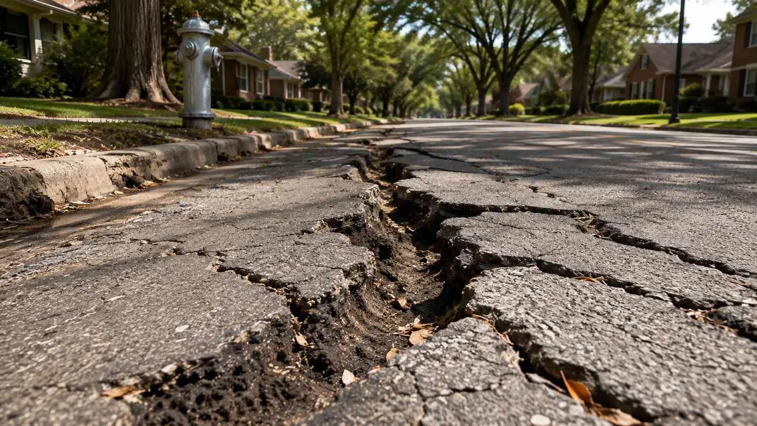
Pavement above utility trenches is often where reactive clay’s effects on buried infrastructure become visible to a developer or municipality long before the underlying utility problem itself is identified, since differential settlement or heaving in the trench backfill transmits upward and manifests as pavement cracking, rutting, or unevenness along the utility trench alignment. This visible pavement distress is frequently a useful early indicator of underlying trench settlement or soil movement issues, and pavement restoration design above utility trenches on reactive clay formations should incorporate this recognition, using pavement section design and trench compaction standards specifically intended to minimize this differential movement risk rather than a standard pavement restoration approach that doesn’t account for the trench’s specific soil condition.
Coordinating Geotechnical Recommendations With Utility Design From the Outset
The consistent theme across every design consideration discussed in this article is that reactive clay’s effects on buried utility performance can be meaningfully mitigated through specific engineering attention, but only when the project’s geotechnical investigation findings are actually incorporated into the utility design rather than treated as a separate deliverable that informs building foundation design while the utility design proceeds on standard specifications developed without regard for the site’s actual soil conditions. This coordination requires the geotechnical engineer’s investigation to specifically address the soil conditions along the planned utility corridors, not just at building footprint locations, and requires the utility design team to actively incorporate those specific findings into pipe material selection, bedding and backfill specifications, trench depth decisions, and joint design, rather than defaulting to a generic regional specification that doesn’t reflect what the project’s own geotechnical investigation actually found.
Frequently Asked Questions
How do we know if our specific Dallas-area site has reactive clay conditions severe enough to warrant this level of design attention?
A project specific geotechnical investigation, including soil borings and laboratory testing for shrink swell potential along both the building footprint areas and the planned utility corridors, is the reliable way to confirm your site’s specific soil behavior rather than relying on general knowledge that a site sits within the broader Eagle Ford or Austin Chalk formation area. Regional geologic mapping can indicate whether reactive clay conditions are likely present, but the specific severity and depth profile of that reactive behavior varies enough from site to site that project specific investigation should inform your actual design decisions rather than a general regional assumption alone.
Does addressing reactive clay conditions in our utility design significantly increase our construction budget compared to a standard installation?
Incorporating imported bedding material, adjusted compaction requirements, and any pipe material or joint design adjustments does add some incremental cost compared to a standard installation that doesn’t account for reactive clay conditions, but this incremental cost is generally modest relative to the cost of post-construction repairs, pipe replacement, or pavement reconstruction that often results when reactive clay related utility problems surface after construction is complete. The more relevant cost comparison is the incremental design and construction cost against the repair and disruption cost of addressing the same problem reactively after it has already caused pipe leakage, settlement, or pavement failure.
If our existing utility infrastructure on a reactive clay site is already showing signs of settlement or leakage, is rehabilitation possible, or does it require full replacement?
This depends on the extent and severity of the existing damage, which should be evaluated through a specific condition assessment, including pipe inspection where feasible, before determining whether targeted rehabilitation of the affected segments or a more extensive replacement is the more practical path. In some cases, addressing the underlying soil movement issue, for instance through improved surface drainage that reduces moisture fluctuation around the affected utility corridor, combined with targeted repair of specific damaged joints or segments, can be a reasonable intermediate approach, though this should be evaluated against full replacement based on the specific condition assessment findings for your infrastructure rather than assumed as a universal solution.
Related Resources
- Sanitary Sewer Overflow Risk in Dallas’s Older Watersheds: What White Rock and Turtle Creek I&I History Means for Infill Developers
- Hydraulic Modeling for Dallas High Rise Developments: Why Pressure Zone Design Matters More Than You Think
- Lift Station Design in Houston’s High Groundwater Zones: Why Standard Specs Fail in Clay Heavy Soils
- Approved Plans Aren’t Always Optimized Plans: The Difference Can Cost $15 Million
Designing Buried Water and Sewer Infrastructure for a Reactive Clay Site in the Dallas Area?
MES works with Dallas area developers, contractors, and engineering teams to coordinate geotechnical findings with water and sewer utility design, select appropriate pipe materials and bedding strategies for reactive clay conditions, and reduce the risk of pipe movement, leakage, and post construction repair on Eagle Ford and Austin Chalk formation sites.
We specialize in:
- Geotechnical coordination and site specific utility design for reactive clay soil conditions in the Dallas area
- Pipe material selection and joint design for water and sewer infrastructure on Eagle Ford and Austin Chalk formations
- Bedding, backfill, and trench design to mitigate shrink swell soil movement risk for buried utilities
- Sewer slope protection and manhole connection design for gravity systems on reactive clay sites
- Thrust restraint and water main stress evaluation accounting for moisture dependent soil bearing capacity
- Pavement restoration coordination and post construction condition assessment for utility trenches on reactive clay formations
Modern Engineering Solutions, Dallas, Texas. Contact: (214) 833-6748 or mod-eng.com
Keep reading
More to read.
Talk to an engineer
Tell us about your project.
An engineer reads it
Not a salesperson. Someone who can tell you whether the pathway is real.
You get a first answer
Your options, the agencies involved and the questions that decide cost and schedule.
You decide
No commitment to have the first call.
Prefer the phone? (214) 833-6748